The work continues to remove vestigial components that supported the internal combustion engine.
The list of removed parts includes the oil tank (and 14 quarts of oil required for the dry sumped, air cooled engine), the oil cooler, fuel vapor canister, fuel filter, fuel pressure accumulator, cruise control servo, starter motor and electronic ignition module.
Twenty feet (6 meters) of copper pipe comprise the oil cooler. The tubes run from the back engine compartment along the rocker panel to the front passenger wheel well. The coiled bit is sometimes called the trombone.
The right rear engine bay cleaned after removing the oil tank. The grease and dripping oil will not be missed.
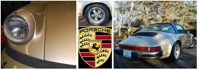
Sunday, February 26, 2012
Friday, February 10, 2012
Extracting the Flywheel
I need to send my flywheel to my EV vendor so that they can make an adaptor for me. The flywheel bolts to the crankshaft of the gas engine. It is a large disk that smoothes out the pulse of the gas motor and it provides a surface for the clutch disk to transfer power to the transmission. With an electric motor, there is no need to dampen power pulses, but the flywheel is still needed to transfer power to the clutch. The adaptor will allow me to bolt the flywheel to the electric motor.
Unbolting the transmission from the gas motor. |
The flywheel is top center, the pressure plate is to the right, and the clutch disk is on the left. The flywheel bolts on with nine bolts. |
Monday, February 6, 2012
Gas Engine Removal
The car has been de-iced. (ICE = internal combustion engine). If you are doing this with floor jacks (some of us don’t have access to a car lift), one tip that saved me a lot of time is to jack up the front of the car a bit, to make it easier for the transmission gear selector shaft to clear the tunnel. Otherwise I followed the process in my service manual, and didn’t have any real problems. I took my time, as this was my first engine removal, and it took about 14 hours working solo.
This is the before picture. |
Draining the fluids and removing all of the connections to the engine (eletrical wires, tubes, cables, drive axles). |
Lowering the engine to the floor. |
Engine is disappearing. |
The back end has to be lifted high into the air. The engine then slides out. |
Smelly, greasy, dirty, gas fueled beast has been liberated from the car. |
Blank EV canvas. It's a beautiful thing. |
Wednesday, February 1, 2012
Brakes
The vacuum kit I ordered for the car arrived today.
Most cars on the road have power assisted brakes. When you press the brake pedal, a brake booster increases the pressure in the brake lines in proportion to the force applied at the brake pedal. The brake booster operates on vacuum, which is available from the intake manifold on internal combustion engines. On an electric car, the vacuum must come from another source – a vacuum pump. On some electric cars, the vacuum pump can be the noisiest part of the car. I found a pump kit that has a reputation for quiet operation: VBS-EV-12 . The pump operates from the car's 12 Volt system. The exhaust of the pump is coupled to an oil filled muffler. This cuts down emitted noise. The pump will be installed with a rubber isolation mount, to keep vibration from transmitting through the structure of the car. If pump noise still proves offensive, then the final contingency is to mount the pump in an acoustic enclosure.
When the vacuum pump is switched on, the pressure in the brake booster drops. Once the proper pressure is achieved, the pressure switch will open and turn the vacuum pump off. Provided there are no leaks, the vacuum level can be passively maintained until the brakes are operated. The check valve prevents the vacuum from leaking through the unpowered pump. After a few cycles of pressing the brake pedal, the pressure will rise, and the vacuum pump will switch on. The purpose of the buffer tank is to store vacuum, and increase the number of times the brakes can be operated before the vacuum pump turns on again.
The electrical circuit will only turn the pump on when the pressure switch measures poor vacuum, and when the ignition switch is in the run position. The main relay is rated for 40 amps. The reason for the second relay is not clear to me. The only thing that comes to mind is that the coil of the main relay must draw a fair bit of current, and the second relay keeps the current drawn from the ignition switch reasonable.
Subscribe to:
Posts (Atom)