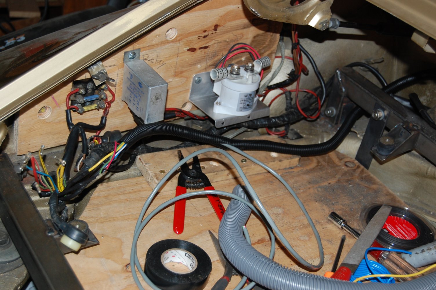
Header

Header
1983 Porsche 911 SC Targa

Sunday, April 28, 2013

Throttle Position Sensor

The throttle position sensor provides a signal to the controller to determine how much voltage and current from the battery pack is passed to the motor. The sensor is an automotive grade potentiometer – a 5,000 Ohm resistor with a sliding contact that measures a variable portion of the resistance depending on position.


The sensor connects to the throttle linkage of the car with a ball joint. When you depress the accelerator pedal (I can’t call it a gas pedal anymore), the arm of the throttle position sensor rotates, sending a signal to the controller to increase the power to the motor.

The sensor needs to be mounted in the same location as the throttle body of the gas engine. The throttle linkage is routed through a bellcrank on the transmission, so I decided to mount my throttle position sensor to the transmission adaptor plate to avoid throttle surging due to torque induced twisting of the transmission during acceleration.

The adaptor plate has a cutout feature at the bolt mount that I used to key the throttle bracket.


Thursday, April 25, 2013

12 Volt Wiring

I need to tie into a number of the car’s 12 volt signals. The controller needs a 12 volt power source that is switched at the ignition switch with the key. The controller makes use of the brake and reverse signals to cut or reduce power output to the motor. The controller can also generate the proper signal to drive the stock tachometer in the instrument cluster. I traced out the signals in my service manual.


It looks like a mess, but I will clean up the appearance by routing the wires in split loom tubing. Once the component placement is finalized, the plywood will be replaced with aluminum panels.

Sunday, April 21, 2013

Tachometer

The Soliton 1 controller that I’m using for this project has an input for a tachometer, and it is a good idea to connect it up because it allows the controller to limit the speed of the motor. On the gas engine, the tachometer was driven by the ignition system. Now that the ignition system is no longer around, the controller fills the void with a tachometer output signal that can drive the original tachometer needle in the stock instrument cluster.

To detect the speed of the motor, I need a sensor and a sensor target. The sensor is an inductive proximity sensor. It is basically a metal detector and a 12 volt switch. If any ferrous metal comes within 4 mm of the sensor tip, the switch closes and 12 volts shows up on the signal wire of the sensor.  The 1 k resistor is called a pull-down and it provides a weak path to ground.  When the switch is open, the output would otherwise float, and this can lead to erractic measurements at the controller.


I purchased a quick change tool post as an upgrade for my lathe so I could make the tachometer target. I’m quite pleased with the results. The turning tools of the lathe are installed into mounts that have a dove tail feature that mates with the holder base. A quick turn of the handle engages a cam that locks the tool securely. The vertical position of the tools can be fine tuned by adjusting the gold colored knob. With the old holder I had to shim each tool, every time I switched tools. The new post is more solidly mounted to the cross slide and carriage, so the finish of the turned parts are much smoother than with the old holder.


The tachometer target is an aluminum ring that fits on the tail shaft of the motor. It is held in place with two bolts. The controller will get two pulses for every complete rotation of the motor as the heads of the bolts swing past the sensor.  


I made up and printed some cards for my project.  Once I start taking the car out into public, I expect it will be a curiosity.  The cards will provide an easy way to refer interested people to this blog.


Sunday, April 7, 2013

Controller Mount and Conduit

Controller

To mount the controller, I made some tabs that are welded to my battery box cross bars. Road vibration is isolated with rubber mounts. I struggled to figure out the best way to mount the controller. The controller was too heavy to easily move around to figure out the geometry.  The controller is on a 10 degree angle.  So, I made a mock up wood frame, mounted the rubber mounts, and the job of locating the mounting tabs got a lot easier.

Close up detail of the tab and rubber mount.  I will grind some material from the tabs to make sure the mount does not cut into the rubber mount when the controller moves around.

The controller is mounted!  I wanted a shot without the plywood, but I will have to disassemble my cross bars first because the wood is currently trapped by the controller mount.

Conduit

Because my battery pack is split, I will have two heavy conductors connecting the front and rear packs. I also need to route 12 volts and AC power for the charger to the back of the car. These cables must be protected from damage – road damage and sharp sheet metal edges.  Noisey power cables will be routed on the opposite side of the car from the signal cables.

Before 1998, the Porsche 911 was air cooled. The heater worked by drawing air through a heat exchanger on the exhaust of the rear mounted engine.  The warmed air was piped to the front of the car via a pair of ducts enclosed in the unibody. Now that the gas engine is gone, the heater ducts are a nice protected space to run electical cable.  Using a steel fishtape and lots of cable lubricant, I pulled two runs of nine foot long, ¾ inch conduit through the left and right ducts (with help from my wife). I tried to get two runs of conduit into each duct, but I didn't get far before concluding that it wasn’t going to happen.

I routed a conduit run just inside the passenger side rocker panel, in a channel that was used to circulate hot oil from the oil tank to a coil in the front passenger wheel well.  It closely follows the path of the heater duct.  This is important because noise can be reduced by keeping the positive and negative power cables as close together as possible.  A twisted pair would be an even better configuration, but it just isn't possible in this case.

I had to make one penetration in the front wheel well to get the conduit into the trunk compartment. A ¾ inch knockout punch makes a very clean hole for the conduit fitting.

I used liquid non metallic flexible conduit and liquid tight fittings that should keep my wiring dry and well protected.

In the front of the car, the conduit exits the heater duct. Check out the mess of ducting, valves and multiple blowers that comprise the heating and ventilation system.

The upper conduit runs along the rocker panel and front wheel well.  The lower conduit runs in the heater duct.