To detect the speed of the motor, I need a sensor and a sensor target. The sensor is an inductive proximity sensor. It is basically a metal detector and a 12 volt switch. If any ferrous metal comes within 4 mm of the sensor tip, the switch closes and 12 volts shows up on the signal wire of the sensor. The 1 k resistor is called a pull-down and it provides a weak path to ground. When the switch is open, the output would otherwise float, and this can lead to erractic measurements at the controller.
I purchased a quick change tool post as an upgrade for my lathe so I could make the tachometer target. I’m quite pleased with the results. The turning tools of the lathe are installed into mounts that have a dove tail feature that mates with the holder base. A quick turn of the handle engages a cam that locks the tool securely. The vertical position of the tools can be fine tuned by adjusting the gold colored knob. With the old holder I had to shim each tool, every time I switched tools. The new post is more solidly mounted to the cross slide and carriage, so the finish of the turned parts are much smoother than with the old holder.
The tachometer target is an aluminum ring that fits on the tail shaft of the motor. It is held in place with two bolts. The controller will get two pulses for every complete rotation of the motor as the heads of the bolts swing past the sensor.
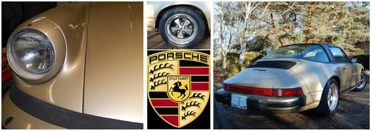
I made up and printed some cards for my project. Once I start taking the car out into public, I expect it will be a curiosity. The cards will provide an easy way to refer interested people to this blog.


No comments:
Post a Comment