Header

Header
1983 Porsche 911 SC Targa

Friday, July 6, 2012

Mounting the Electric Motor in the Car

There are four stock mounting locations on the car for mounting the motor and transmission. The mounting points utilize a hard rubber to isolate the car from motor vibration. They are engineered to take the twisting load of a motor under acceleration, so I would like to reuse the mounts for the electric conversion. I'm also reusing the stock cross bar to connect to the rear motor mounts.


I needed a way to locate how the rear cross bar is positioned relative to the electric motor. The geometry is important to ensure suspension travel and drive loads are the same as with the gas engine. Taking measurements on the gas motor proved to be difficult, so I made a jig that connects to the transmission mounting flange on the gas engine block, wraps around the engine, and bolts to the cross bar.


The jig is then mounted to the transmission flange on the electric motor adaptor plate. The cross bar is held in the correct position and I can connect the electric motor to the cross bar with a metal bracket.


To start on the bracket, I made a disk out of 1/4 inch (6 mm) steel plate to bolt to the end of the motor with 4 bolts on a 6 inch (150 mm) diameter, 90 degrees apart. I have never had good luck with precision drilling. I always end up drilling the clearance holes larger to account for placement error. This compromises the strength of the bracket because some bolts will be loaded more than others. I did some research and was able to place the holes very precisely using this technique: lay out the holes using a digital caliper. The first hole is marked by measuring off 3 inches from the center. The next hole is marked by scribing a line 3 inches from the center mark in the general location of where the second hole should be placed, and another line 4.243 inches from the first hole. The intersection of the two scribe lines marks the center of the second hole. All four holes are marked and double checked. Next, a center punch is used to make a small indentation into the metal surface at the center of each hole location. The first punch mark is made very lightly, and if the location is off a bit, a second strike, with the punch angled toward the correct location, can make a deeper pit closer to the correct location. A drill bit tends to “walk” when starting a hole on a flat surface. The punched dimples provide a little well that holds the drill tip in the correct position while the hole is drilled. The result was amazing. No need to enlarge the clearance holes. 

I used 2 inch (50 mm) square tubing to span the gap to the cross bar. Some metal tabs were added to bolt the assembly to the cross bar. For now the parts are just tack welded, in case any adjustments are needed later.

In the lower left corner is an additional cross member that will be welded in between the two "L" brackets, once I test the fit, and fully welds all of the joints.

The motor and transmission were installed in the car.  After checking the alignment, I will remove the parts, weld them up fully, and paint them.


Here is a video of the wheels spinning for the first time under electric power. The motor is connected to a 12 volt battery with jumper cables.


Tuesday, June 12, 2012

Joining the Motor and Transmission

This is one of the major milestones of the project. I could not have completed this step without the help of my friend Pat, who is a talented joke teller and equally good machinist. Some of the parts I ordered needed modification, and with Pat’s help, we modified them to make everything fit together properly.  Thanks Pat.

The goal is to build up the motor to make it look like the gas engine block. The important parts are the hub, which spins with the crank shaft, and the mounting flange for the transmission.

The first part to go on the motor is the taper lock bush. This piece has a slight taper, and as you bolt it together with the hub, the taper provides a clamping force that grips the motor shaft. This is one of the most secure ways to mount a hub to a shaft. I used a dial indicator to keep the face of the hub square to the motor shaft, as I tightened the mounting bolts (marked 1, 2, and 3 in the photo). Any error here will cause the flywheel to wobble and the vibration will be annoying and cause excessive wear in the drive train. I was able to get the wobble down to 0.003” (75 microns), and run out down to 0.002” (50 microns).


Next the adaptor plate is installed. This mechanically provides a surface to bolt the motor to the transmission.
 
The flywheel is bolted to the hub.


The clutch is centered on the flywheel with a special alignment tool.

Then the pressure plate is added. The clutch is squeezed between the flywheel and pressure plate, and transmits power from the motor to the transmission. When the clutch pedal is pressed, the pressure plate is pulled away from the clutch disk and the motor and transmission are de-coupled, making it easier to change gears.


Here is a video of the clutch spinning up:

The motor is then mated to the transmission.


 Applying 12 volts to the motor spins the output shafts of the transmission:


Saturday, May 26, 2012

Welder

Never waste the opportunity of using a project as an excuse to buy new tools. A lot of fabrication will be required making racks to hold all of the batteries I plan to use. I will also need to make a mount for the new motor. So, I purchased a MIG welder.

Welders join metal by heating the joint above the melting point of the metal. The heating is done by passing current across an air gap between the joint and the welder tip. An arc is formed, and as the sparks fly, some of the metal is vaporized. The welder replaces this with a filler metal. In the case of a MIG welder, the filler metal is a spool of wire fed through the tip of the welder. An inert gas is sprayed around the metal joint to protect the metal from oxidation while the metal is molten.

What is the first project to make with the welder? A welding cart of course. The goals of the cart are to make the welder mobile (the transformer in the welder is heavy), and to store all of the accessories in one location.

My 2 year old son is car crazy.  He loves car shows (Disney's Cars, Top Gear), toy cars, and playing in the Porsche.

Sunday, May 13, 2012

Component Layout Planning

There are several activities going on in parallel with the car. They involve painting, water proofing and setting up a new welder so that I can make some of the car parts myself.  Details will be coming soon.

A friend from Minnesota was in town and he wanted to take a look at the car. He asked a very important question, “Where are you going to put all of the batteries?” I’ve been wondering the same thing. I made a few drawings in Google Sketchup. I want to fit 86 cells into the car.  Each cell is 5.59" x 2.64" x 8.58"  (67 mm x 142 mm x 218 mm).


32 cells will fit on the sides of the motor – 16 on each side.


Another 20 cells can fit across the top of the motor. I need to leave room for the motor controller.


35 batteries can fit in the space at the front trunk where the gas tank once resided.

Once I get the motor and transmission mounted in the car I will make cardboard mock-ups of the batteries. After I finalize the placement, I will design the battery racks.

Wednesday, April 25, 2012

Transmission Maintenance

There are four transmission seals that I replaced – the input drive shaft, two output drive shafts, and the gear selector shaft. The seals must prevent gear oil from leaking out and allow the shafts to rotate freely. I also changed the gear oil. The throw out bearing fork came in my clutch replacement kit.
 
Old worn out parts that were replaced - clutch spring, oil seals, clutch release fork, and jack port covers.


New clutch release fork installed in the transmission bell housing.  I had to file down some of the casting flash at the top and bottom of the bore to get it to fit.
Because I am keeping the transmission in my EV conversion, I cannot eliminate all of my oil use with this car, but usage is greatly reduced because the oil in the gear box is not changed nearly as frequently as oil in the crank case. There are AC electric motors capable of going without a gear box (direct drive or fixed gear). They are used in most commercial electric vehicles. AC is cost prohibitive to most home hobbyists converting their own cars. The DC electric motor I selected has a wider torque band than the gasoline engine, but not wide enough to eliminate the need for a transmission. I expect to use 2nd gear to accelerate up to 45 MPH (70 km/hr) and 3rd gear at greater speeds. The reverse gear will also be required. In addition to being more economical, the DC motor will have more torque available at low RPM compared to AC electric and gas engines – peak torque is available from 0 to 2500 RPM.

Friday, April 20, 2012

Motor Break-in: Seating the Brushes

The series wound DC motor doesn't contain any permanent magnets.  There is a set of coils attached to the motor body in an assembly called the stator, so named because the stator coil is stationary.  There is another set of coils attached to the motor shaft in an assembly called the armature.  These coils rotate with the motor shaft.  The two sets of coils are wired together in series.

When current passes through the coils, a magnetic field develops, and the armature and motor shaft  rotate until the magnetic field in the armature aligns with the fields in the stator. The electric motor will not continue to spin unless the magnetic fields change. The current flow in the coils must be reversed. This switching process is done mechanically inside the motor. Electricity flows to the armature coils through brushes that are pressed against a cylinder (commutator) that is composed of electrically isolated segments.  Each segment is electrically connected to the armature coil.  As different segments of the commuter come into contact with the brushes as the motor shaft rotates, the current in the coil changes in a way that the magnetic field in the motor advances.  The motor shaft will contiue to chase the moving magnetic field, allowing the motor to continuously spin.

The electric motor is capable of drawing over 1000 amps of current, so it is important that the brushes make good electrical contact with the commutator to minimize electrical resistance and heat problems. The brush seating process entails operating the motor without a load at a relatively low 12 volts, for 40 hours to finely shape the brushes against the commutator.


The electric motor is strapped down securely for seating the brushes with a 12 volt run-in procedure.


Saturday, April 7, 2012

EV Adaptor Plate, Hub and Motor Arrive

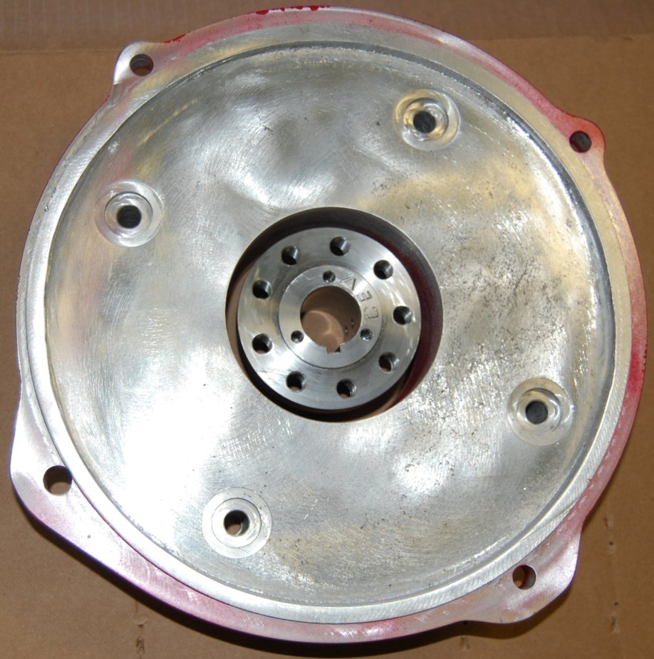
My adaptor plate and hub arrived. In 1978, Porsche switched the design of the flywheel from a 6 bolt to a 9 bolt design. The supplier had yet to encounter a order for a 9 bolt version, so I sent them my flywheel so they could measure the proper dimensions for the hub. The adaptor plate connects the bodies of the transmission and electric motor. The hub connects the rotating shaft of the electric motor to input shaft of the transmission.

Now that I have the flywheel back, I took it to an automotive machinist to have it resurfaced and balanced. The machinist was an interesting man. He works on Cosworth racing engines and he restores T-28 Trojan aircraft – a US military plane used to train Air Force and Navy pilots in the 1950’s. The shop was located in an aircraft hanger, and it was packed with machine tools, engine blocks, and several aircraft in various states of restoration.
The motor bolts to this side of the adaptor plate.  The hub bolts to the motor shaft.


The transmisiotn bolts to this side of the adaptor plate.


The Warp9 electric motor is beautiful.

Out with the gas and in with the electric.